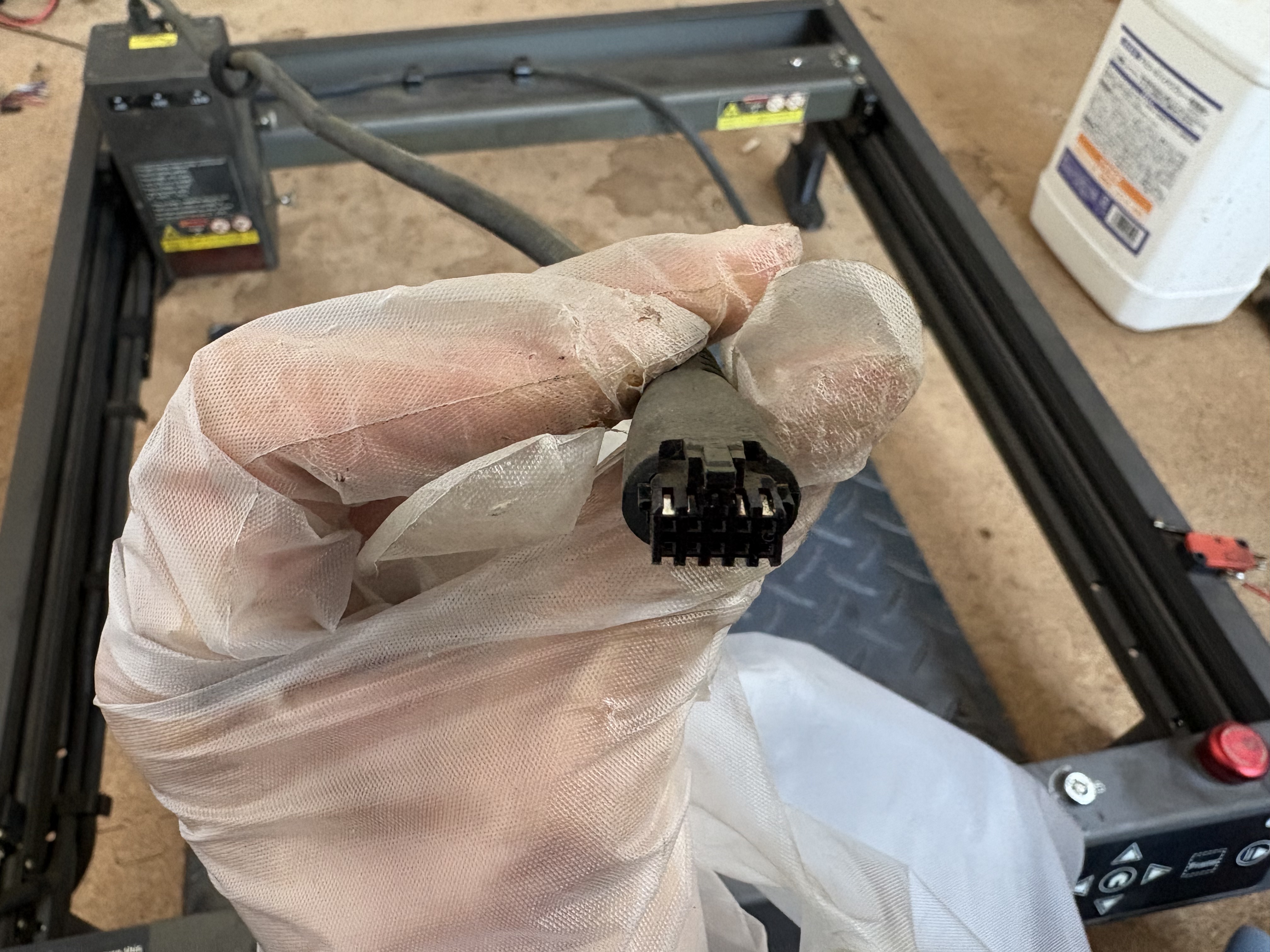
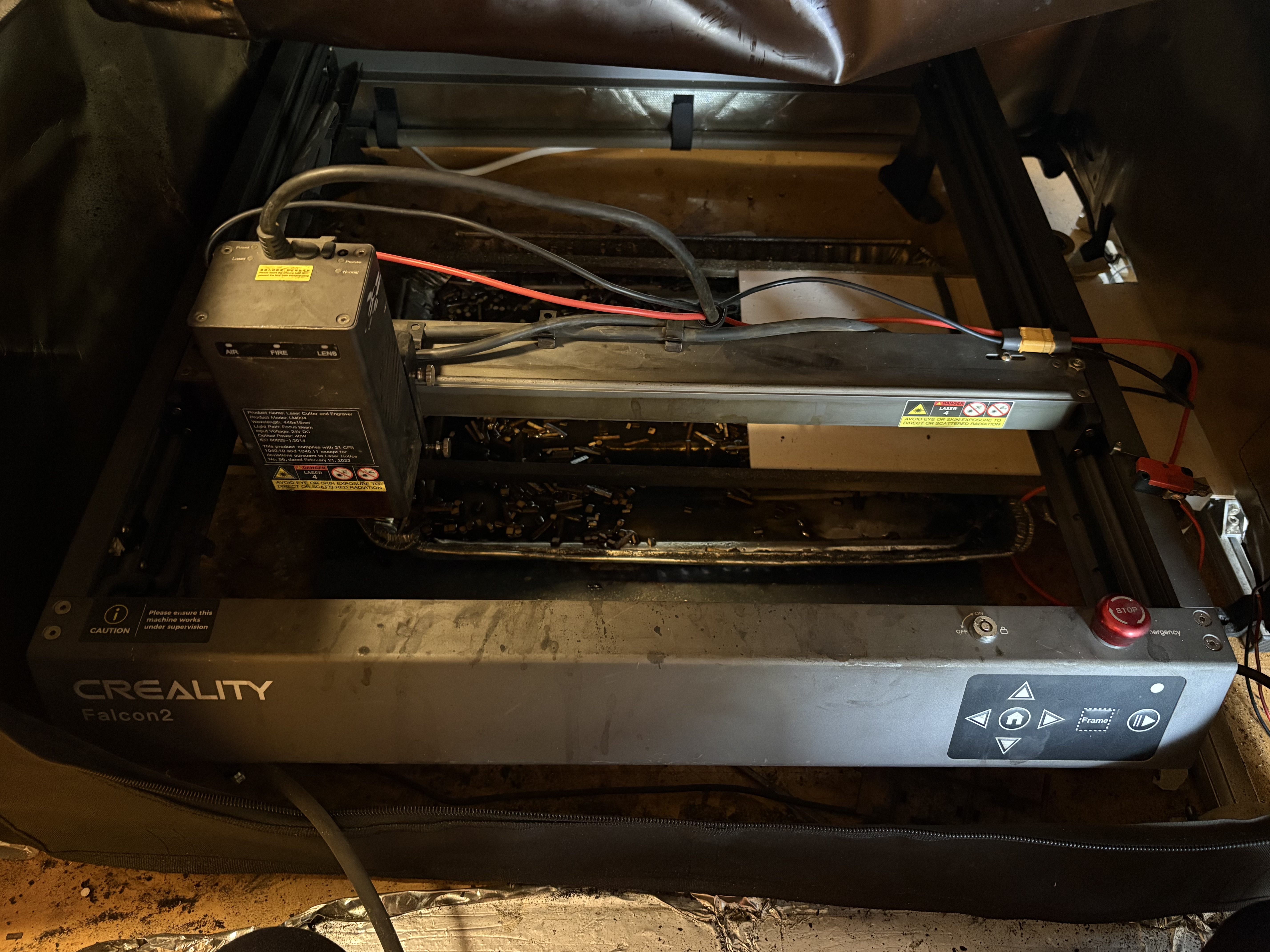
If you happen to be an extreme power user of the Creality Falcon 2 (ie running it for hours on end every day), you might run into the problem of burnt pins. The main reason for this is that all the power gets passed through the three pins on the top right of the laser connector. To get around this, we can direct the power through thicker wire, so that these three pins aren’t taking so much load.
Disassembly
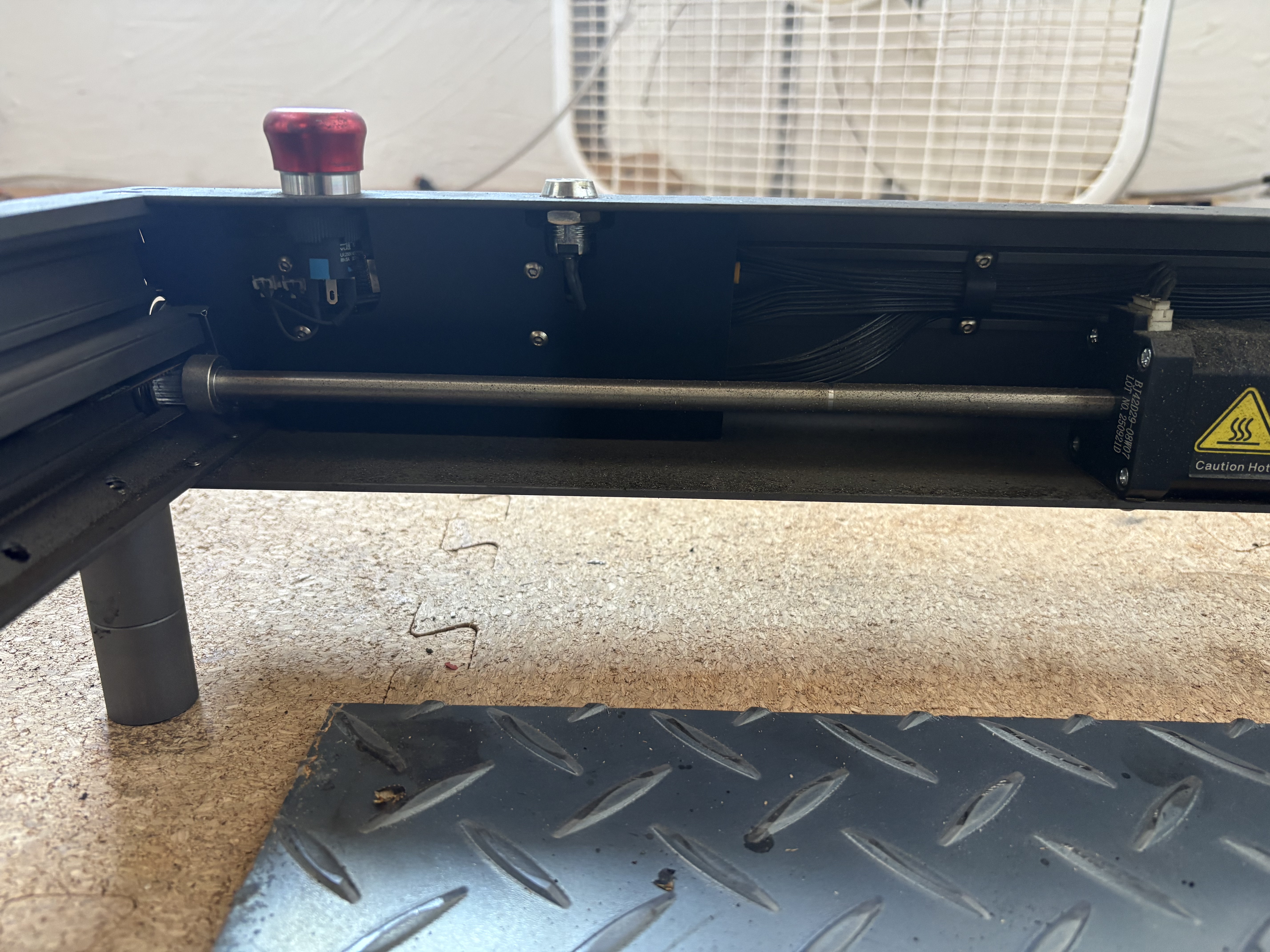
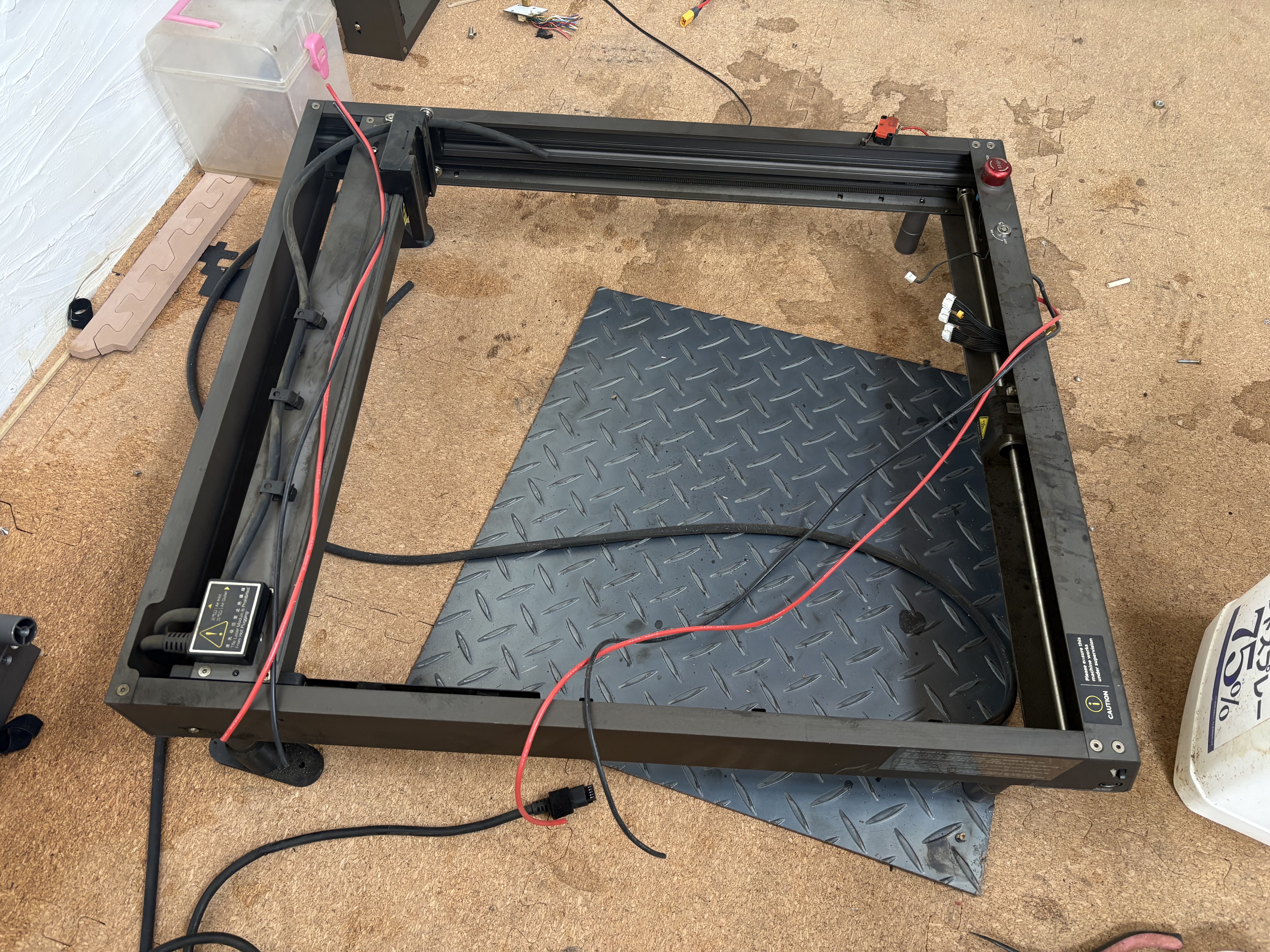
To begin, we must disassemble the main microcontroller located under the Emergency Stop button. You can do this by taking apart the laser frame, but it’s a lot easier just to remove it directly. The microcontroller is protected by a thin sheet that we can remove by unscrewing 4 screws.
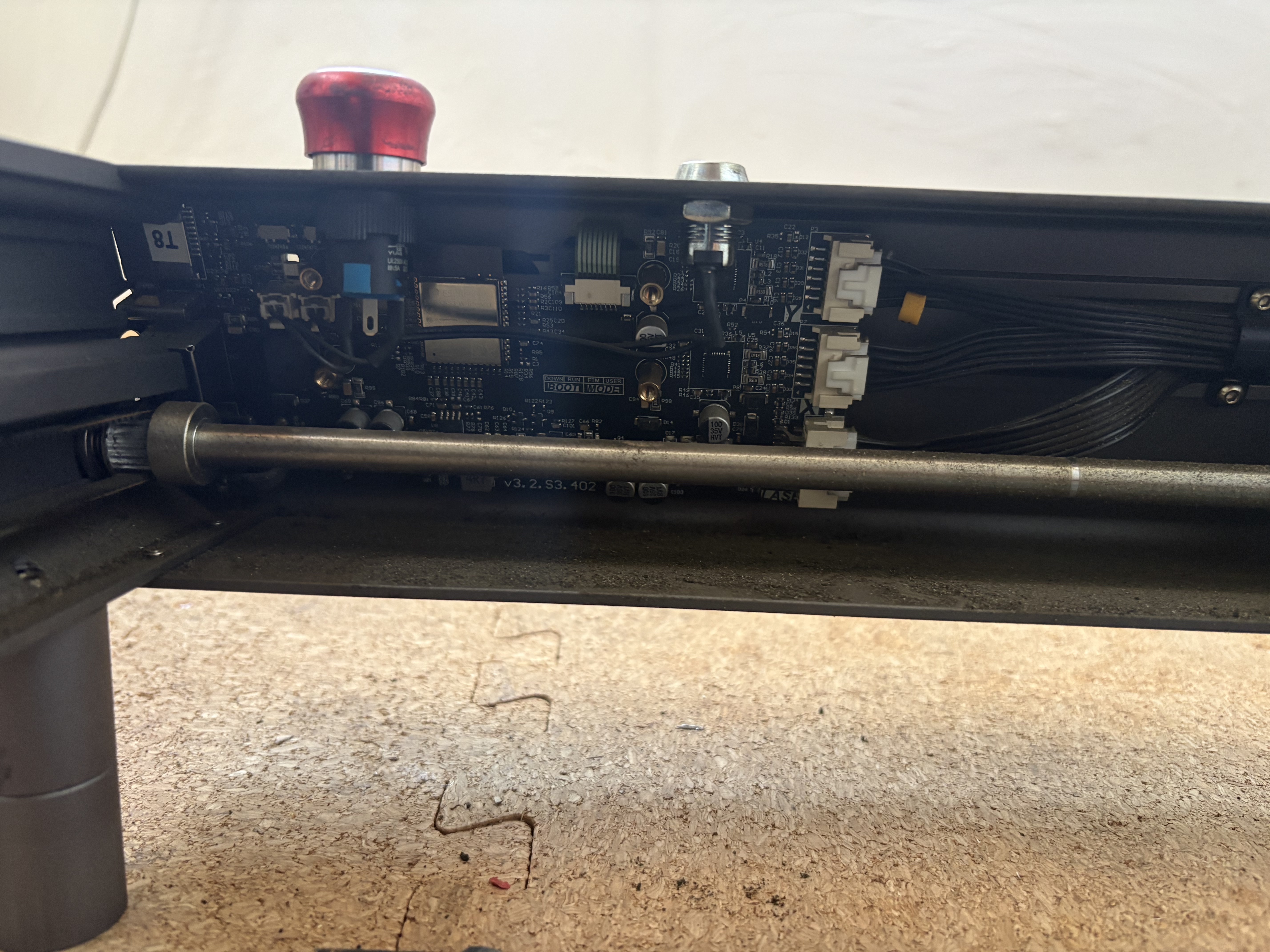
After that’s off, we only need to unscrew the four golden standoffs. You can do so with a set of pliers - just be very careful not to damage any PCB components. Be especially cautious of the capacitor below the top right standoff.
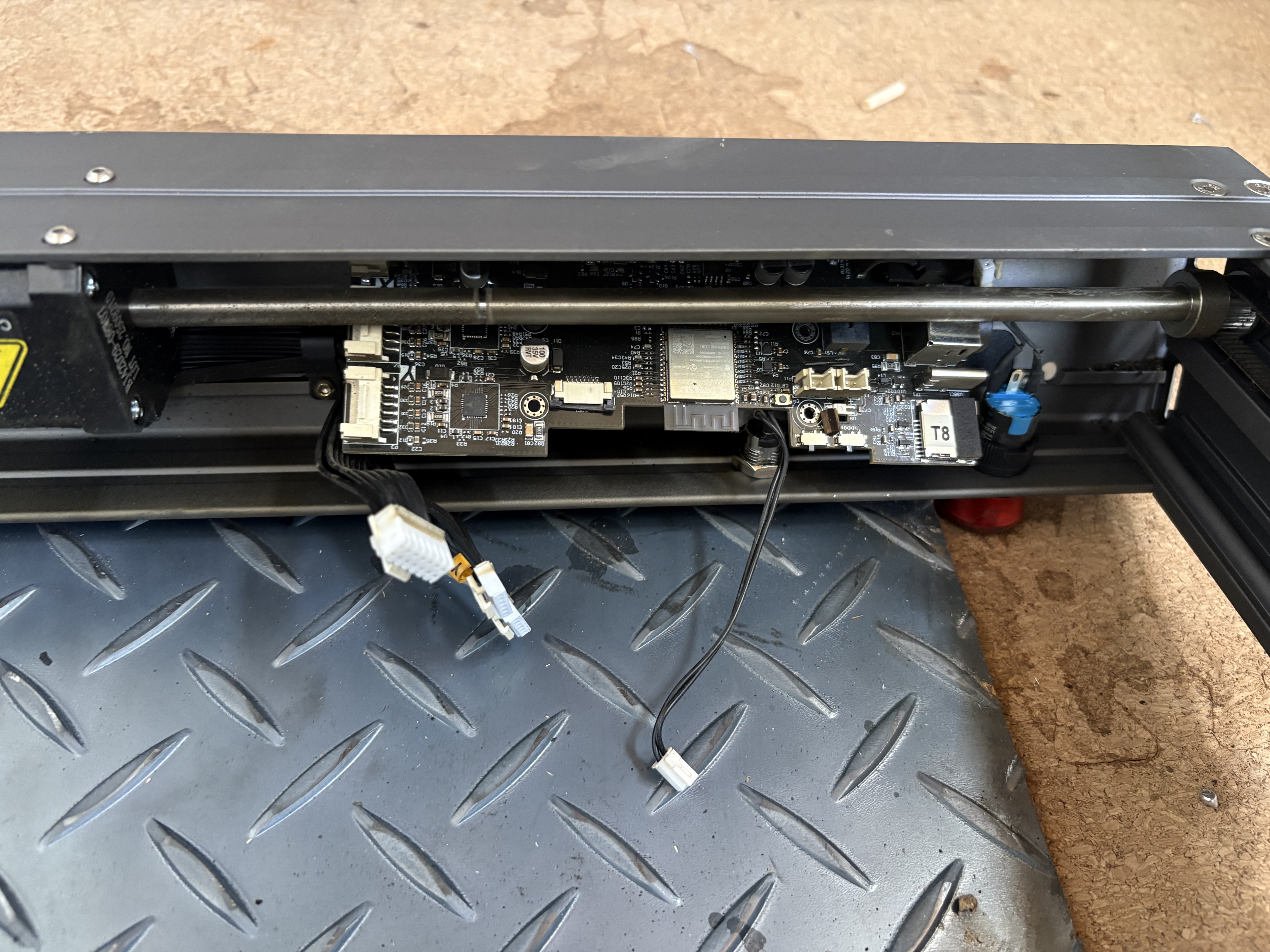
Once that’s off, disconnect each of the 5 connectors by squeezing and sliding out. Also disconnect the green ribbon by pulling up on the small n-shaped tab and sliding the ribbon out. At this point, you should be able to slide the PCB board sideways and into an angle where you can shimmy it out from behind the axle. You will have to pull back on the wires in the way. Be careful not to apply any pressure to the PCB board - just firmly obstacles out of the way instead.
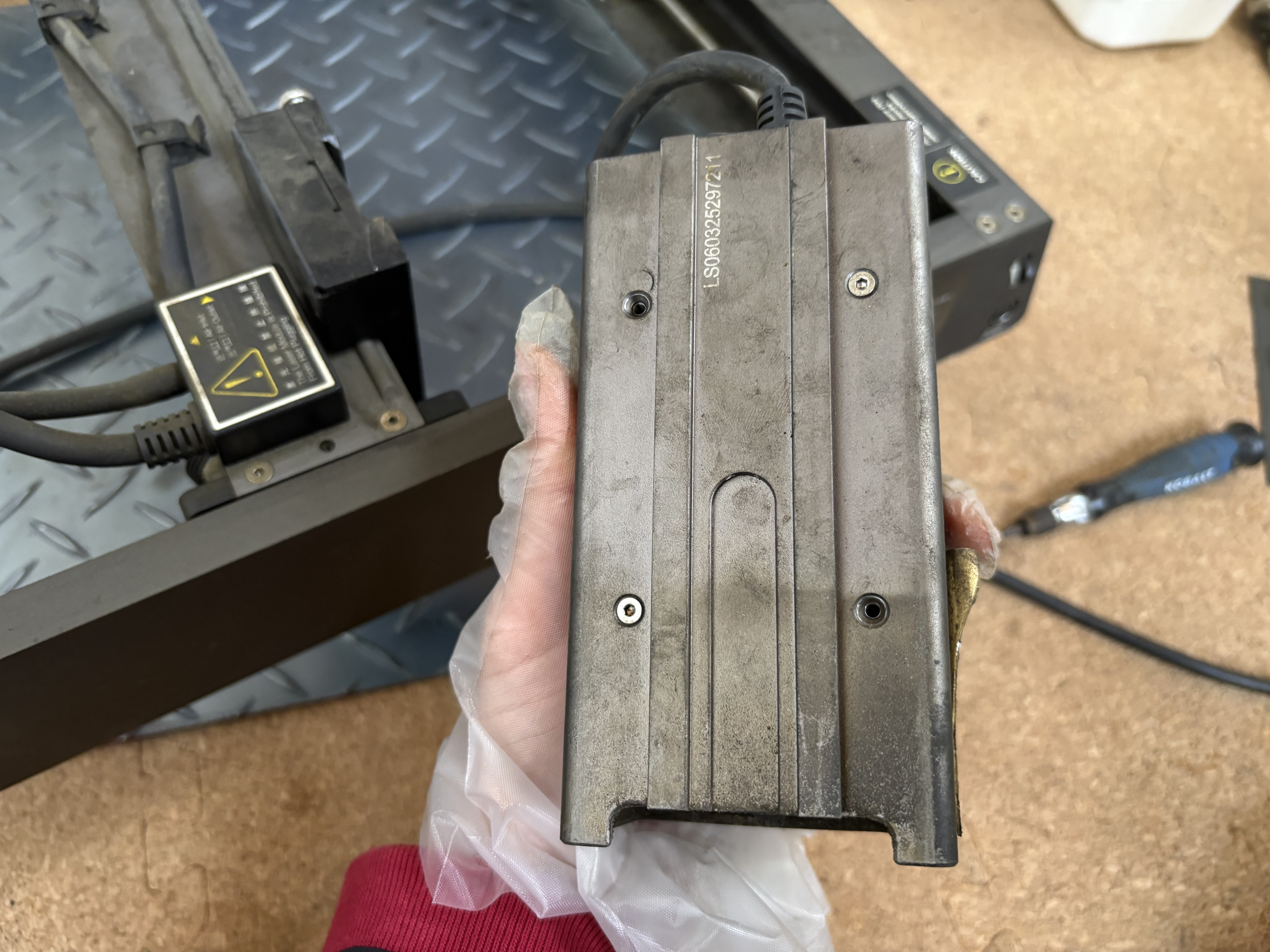
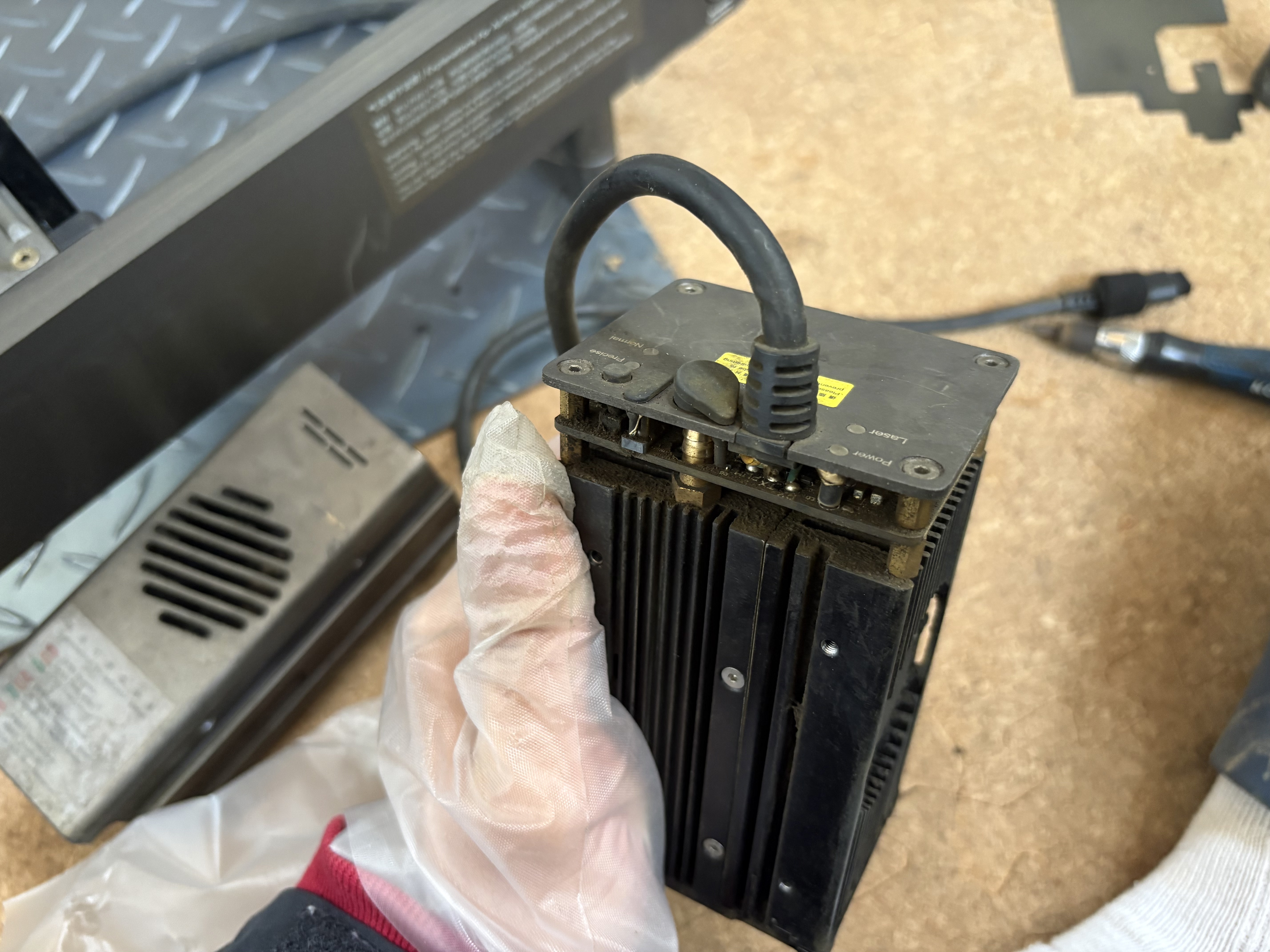
We need to do the same with the laser. This shell comes off after unscrewing 4 screws.
The screw should slide off pretty easily. Feel free to dust any ash off the fans and sensors here.
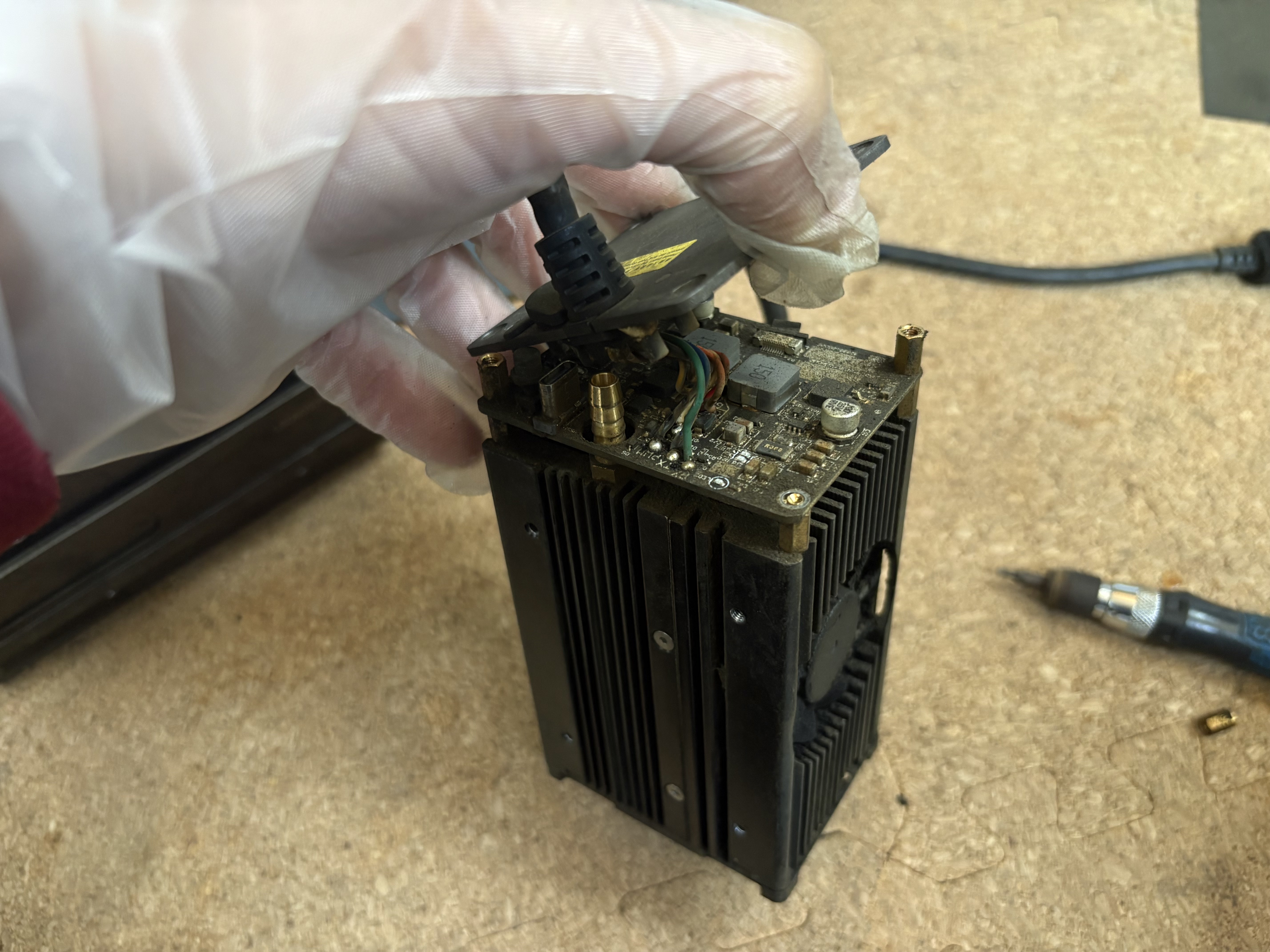
We unscrew the top four screws in the same way, and remove the standoffs via pliers again too.
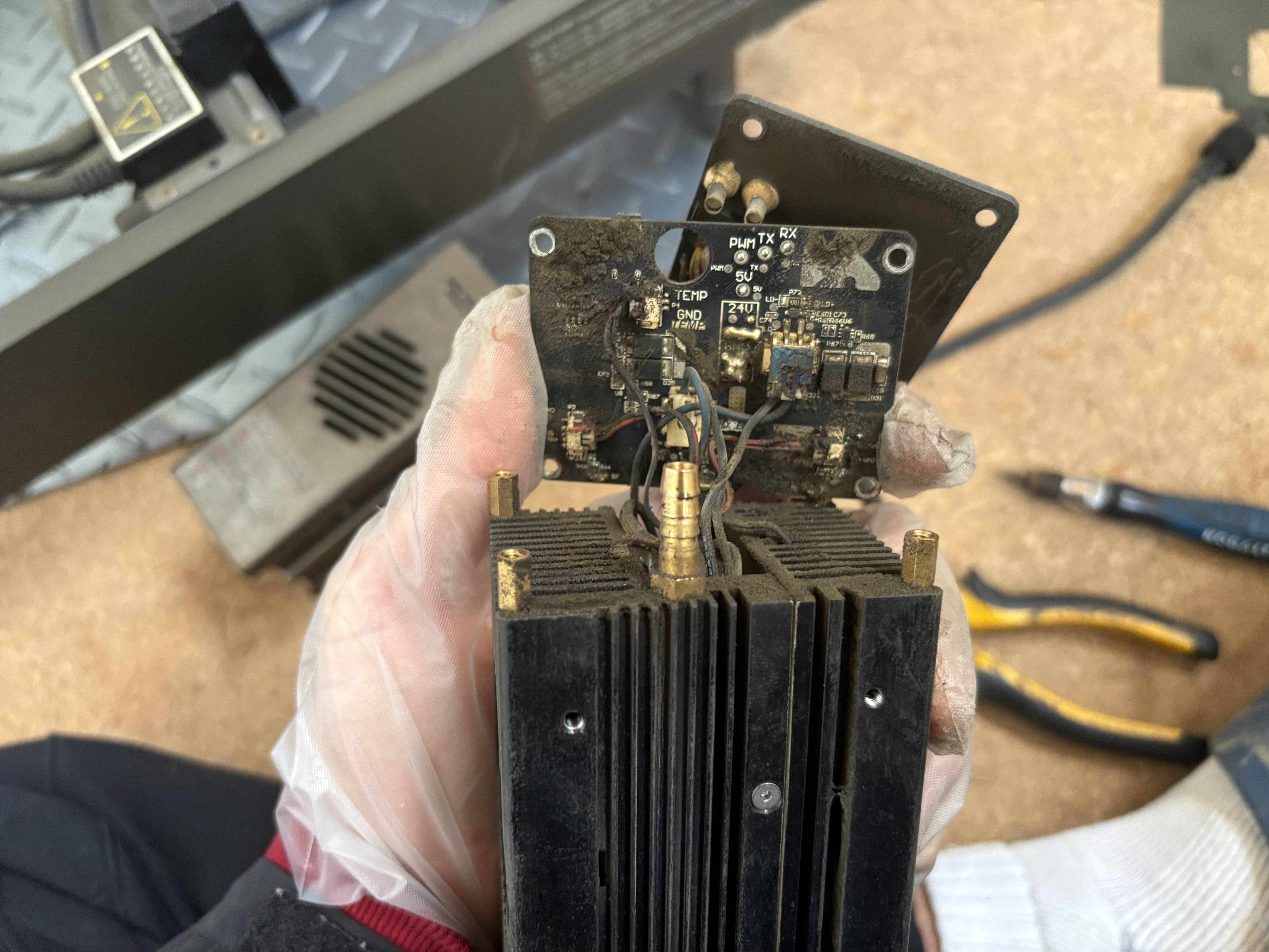
If the PCB board is dirty, take some rubbing alcohol and clean the 24V and GND area so that it’s visible. Carefully disconnect the 4 connectors and ribbon as well.
Wires
Now, it’s time to prepare the wire! RC car wire is used here, but something less thick should work fine as well. Make sure you have a strong enough soldering iron for this step (400º C is ideal). The PCB board and thick wire both wick heat very easily.
If you still want to be able to disconnect the laser head from the frame, you’ll want to use two sets of wires for this part. Measure approximate lengths as seen above.
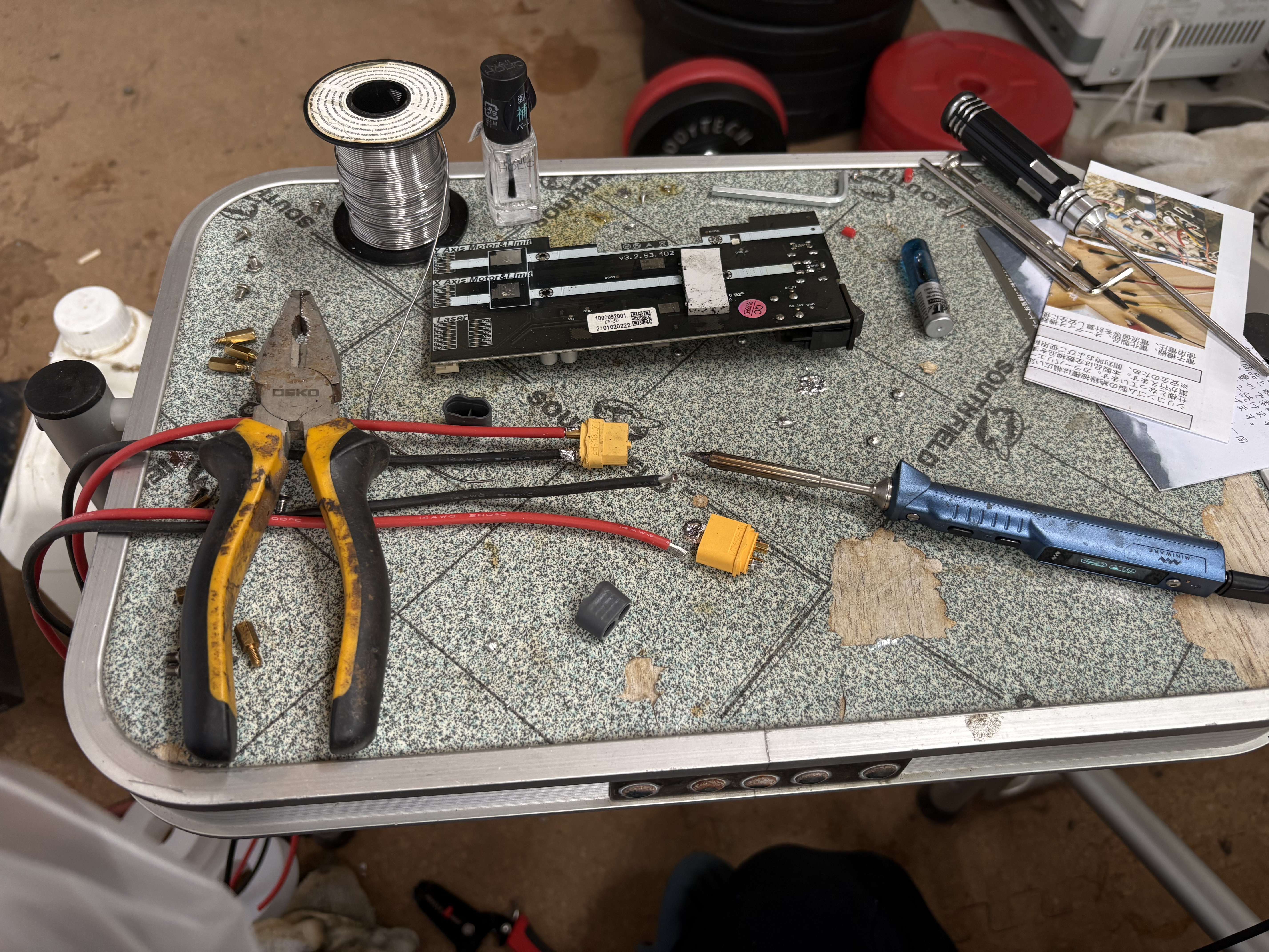
On one end of each pair of wires, solder to a connector. It helps to apply flux on both the wire and the connection area, and a little solder on each, before mashing them together.
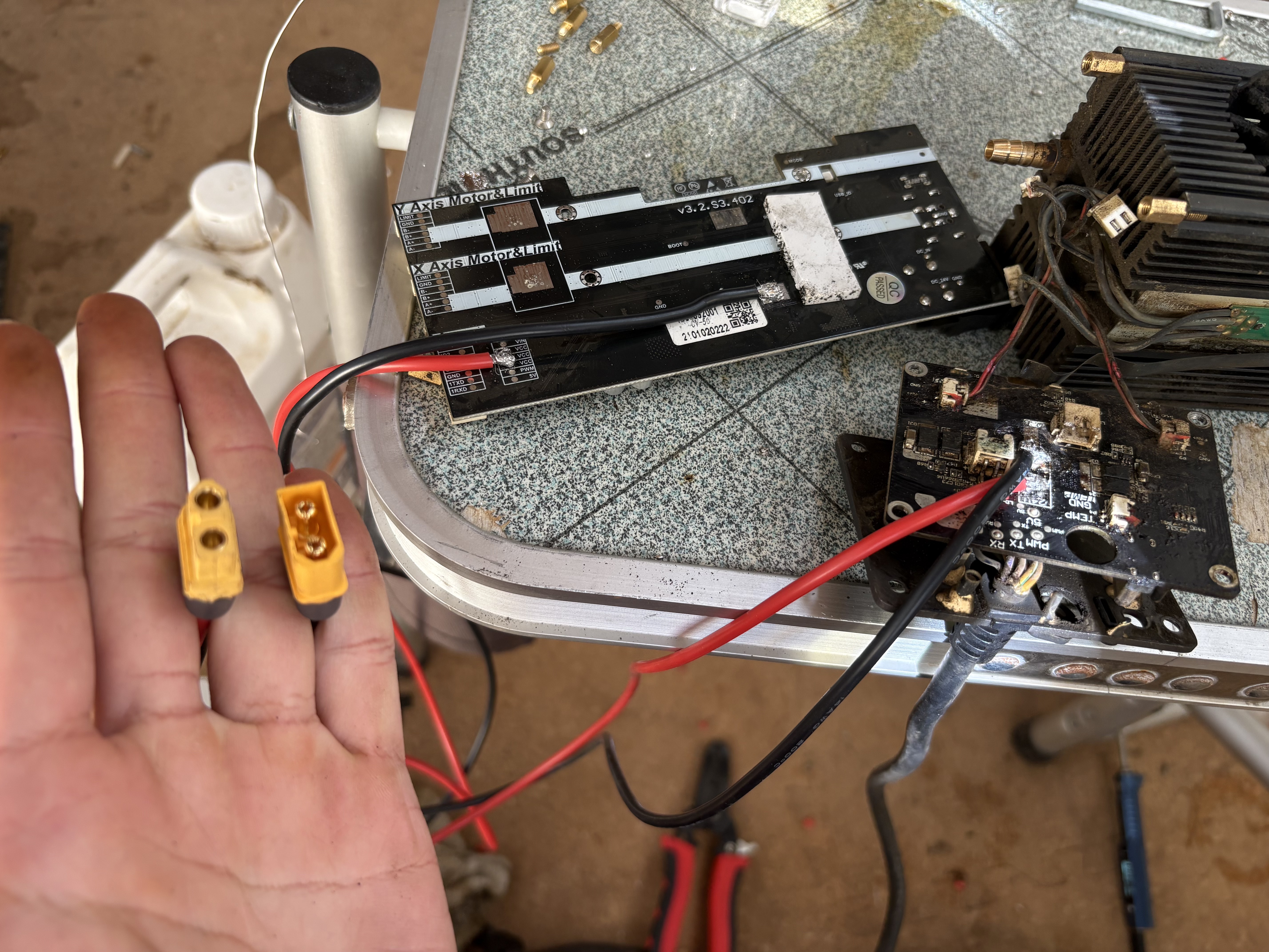
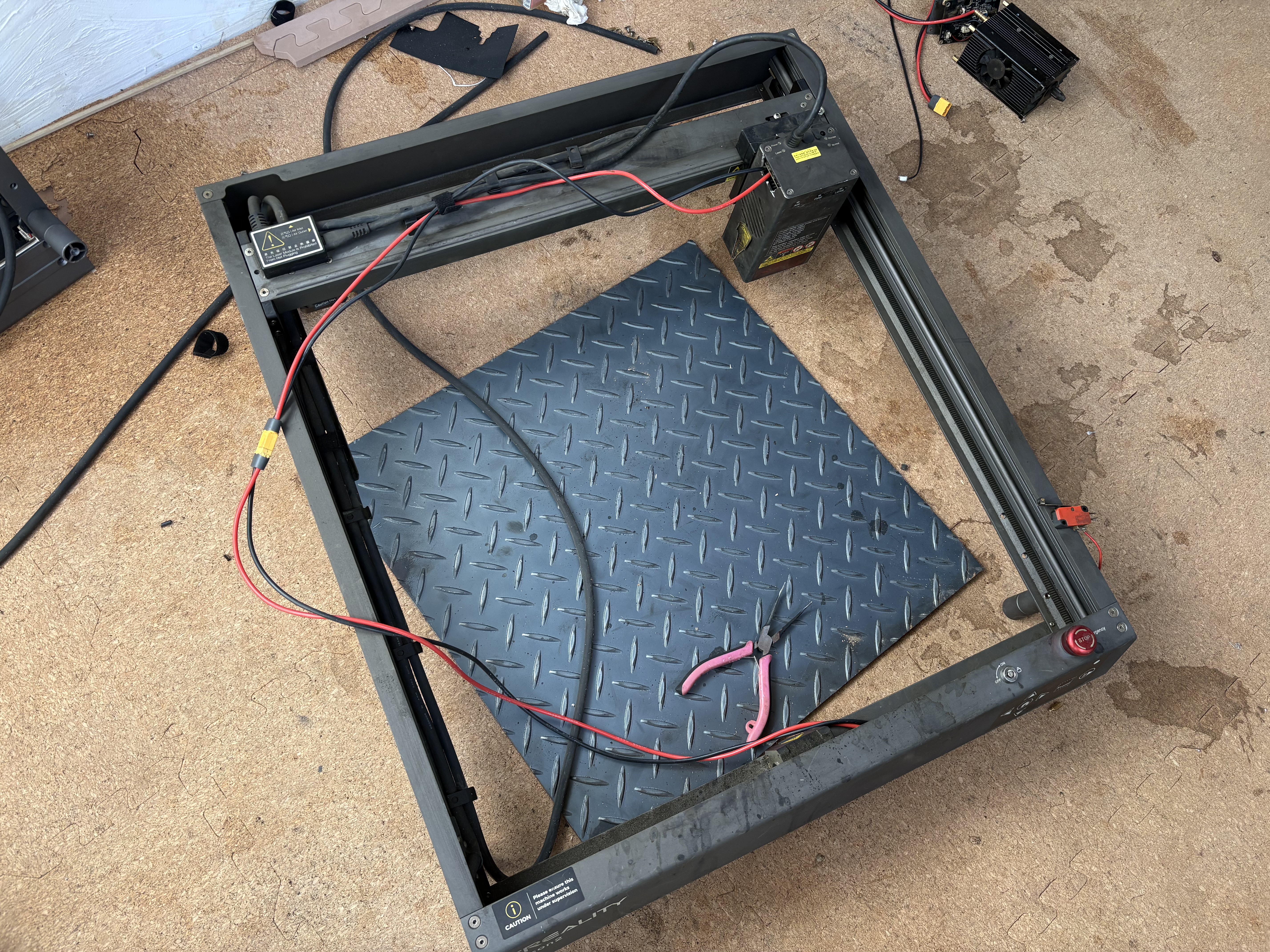
Next, we solder the other end to the PCB boards. Add solder to the PCB board first until some stick, and then solder the wire on. The main microcontroller connects all 3 VCC pins to the positive wire, and attaches to a ground pad. The laser head PCB connects to the 24V and the GND. Be careful not to block the laser connector opening when you solder, and also be careful not to short circuit the two wires. Consider adding a generous layer of clear nail polish over each connection point.
Cutting a hole
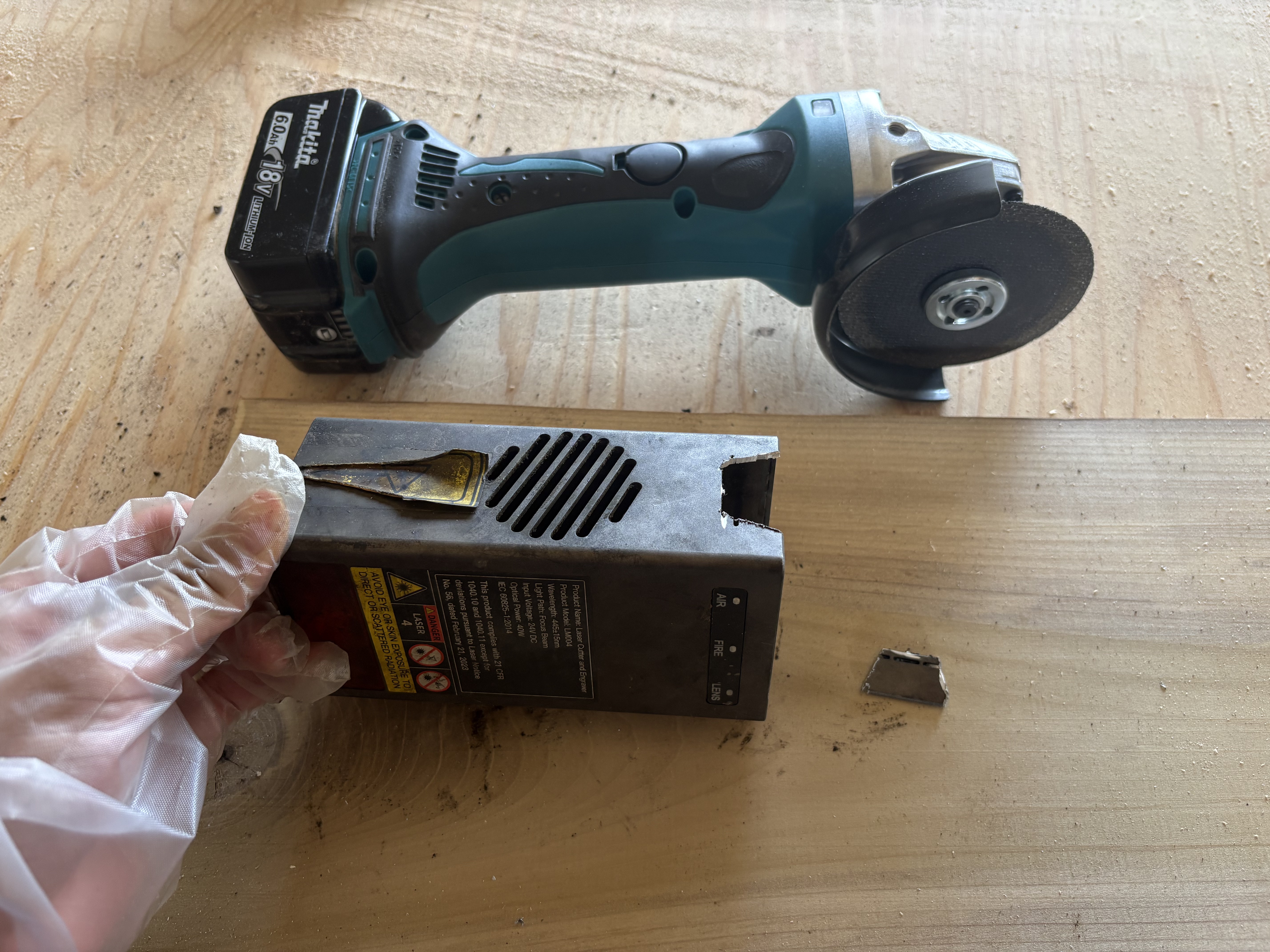
Finally, we need to cut a hole for our new laser wires to snake through. In this case, the orientation is on the left side. You can cut over the existing ventilation holes.
Reassembly
Finally, put everything back together and test! Be careful when installing the main microcontroller back in - there’s wire on the back of it now, so the standoffs may be harder to fit in (one or two standoffs should be fine). If the laser is acting funny, check to make sure the modes are set properly (two switches, top left of PCB board) - the first should be switched to the right and the second to the left.
Adjust the wiring so that it doesn’t get caught when the laser moves around :)